Saturday, December 28, 2013

QtCreator and linking minGW .a libraries

Started with my coding side project again and messed with the linking of .a shared library files. These "archive" files are the same thing as Visual C++ .lib files, but QtCreator does not like them and so they must be manually linked. Lib files can be added through dialog.

First step that I failed to do (really basic mistake :)) is to export the functions in dll in the first place. Otherwise one can link to libraries forever and still get unresolved errors. To export functions or classes in Qt Creator library project, simply add Q_DECL_EXPORT to function or class declaration in header. For example: int Q_DECL_EXPORT mult(int a, int b);

Next thing is to figure out, how to add .a libraries to .pro file so that they link. I found it out with a round trip as I tried to generate .lib based on existing .dll. This is actually really simple and involves a few steps (tips from page http://adrianhenke.wordpress.com/2008/12/05/create-lib-file-from-dll/):
  • open Visual C++ command prompt: Start -> Microsoft Visual Studio 2010 -> Visual Studio Command Promt;
  • type command: dumpbin /exports C:\yourpath\yourlib.dll
  • this dumpbin command actually gave me a sign that my functions are not exported as they were not listed in output
  • copy the names from this section:
ordinal hint RVA      name

1    0 00017770 jcopy_block_row
2    1 00017710 jcopy_sample_rows
3    2 000176C0 jdiv_round_up
4    3 000156D0 jinit_1pass_quantizer
5    4 00016D90 jinit_2pass_quantizer
6    5 00005750 jinit_c_coef_controller
...etc
  • paste names into a text file with .def extension and add EXPORTS as the first line:
EXPORTS
jcopy_block_row
jcopy_sample_rows
jdiv_round_up
jinit_1pass_quantizer
jinit_2pass_quantizer
jinit_c_coef_controller
  • run command: lib /def:C:\mypath\mylib.def /OUT:C:\mypath\mylib.lib
  • copy lib file to include directory and add it using Qt library adding dialog: right click in .pro file and "Add Library...
The added command block can also understand .a files so you don't actually need to create .lib files. It looks like this:

win32:CONFIG(release, debug|release): LIBS += -L$$PWD/include/ \
    -lsimplemaths
else:win32:CONFIG(debug, debug|release): LIBS += -L$$PWD/include/ \
    -lsimplemaths
else:unix: LIBS += -L$$PWD/include/ -lgraphclasses -lsimplemaths
INCLUDEPATH += $$PWD/include
DEPENDPATH += $$PWD/include

The -l addition in the beginning replaces the "lib" part in library file name, so "libsimplemaths" becomes "-lsimplemaths".

Basically this is it but it took me some hours to find out why my simple dll does not link. Tried VC++ dll's and lib's also but there are other problems with compiler differences and they don't work with minGW.


Tuesday, November 26, 2013

Running Synology DSM on virtual machine

This post will be about running modified Synology Diskstation Manager on a virtual machine and thus emulating a NAS that can be accessed through web and managed like an ordinary Synology device. The modified version of DSM is called XPenology and it can be found at xpenology.org It can take some fiddling to get it to work (took me a few hours) so I better make a post about it before I forget :)

Primary steps involved are:
1. Creating a new virtual machine using Oracle VirtualBox
2. Booting the VM with disk image that comes with XPenology download
3. Accessing virtual diskstation and installing modified DSM on it
4. Everything works... or not

Creating a new virtual machine

First step in creating a virtual NAS is to create a new virtual machine that can run Synology software. Diskstations run on 64-bit Linux OS, so virtual machine must also be set up as a Linux machine. I used Debian 64-bit, but others could also work.

There are two main things to set up for VM and host computer: boot disk image and network adapter settings. VM boot device must be an existing IDE device that points to disk image downloaded from XPenology forums. Network adapter must be first set up un host computer by creating a bridge between Oracle VirtualBox Network and Local Area Connection. Select both of them in the list of networks, right click and select Add Bridge (or something similar). In VM settings, navigate to network settings and select Birdged Adapter as network adapter. Name should be the name of the bridge and under advanced settings, set MAC address to either 00113208D63C or 00223208D63C. First one is suggested in different forums, but it didn't work for me (more on that later).

When network settings and boot image are all set, start the VM. It should boot up and end up showing "Diskstation login:"

Installing modified DSM on VM

Start up Synology Assistant and search the network for Diskstations. If all goes well the VM will show up as DS3612xs device. Right click on it and select "Install". Point to the downloaded modified version of DSM, fill necessary fields and start the install.

To be continued...

Monday, November 4, 2013

Nuke 7 plugin development

Today I started setting up the dev environment for Nuke 7 plugin development. As I bumped on some small obstacles, I thought I'd better make a post about it.

Nuke 7 plugins should be compiled with Visual C++ 2010 and if you have 64-but OS then against 64-bit libraries. The thing that gave me a little headache was the 64-bit environment. Nuke installation contains an example project that you can load and that should ideally build without problems. But problems I got...

First problem was in VC++ with setting additional dependencies. Nuke plugins need header files and .lib static libraries from Nuke program folder that must be manually added. For some reason VC++ did not want to show me the project properties dialog. After some messing around I found out this was because I didn't have x64 environment set up and so VC++ did not understand the project settings.

To set up the x64 stuff Windows x64 SDK must be installed. There came the second problem. Both the web installer and ISO image installer gave strange cryptic errors. After some more messing around I discovered that it was due to a conflict with already installed 2010 redistributables. I uninstalled all 2010 packages and after that the SDK installed without problems.

Now VC++ allowed to change project settings and add additional dependencies. In addition to Nuke libraries and headers, Windows SDK lib folder must also be pointed to in linker settings. It must be the x64 sub-folder because otherwise you get the linker unknown external symbol errors.

With all things set up I was able to successfully compile the example project:


Monday, October 14, 2013

New books: one here three to go

Checked my company account and found that I can afford some more interesting and useful books. Using Krisostomus web store I ordered the following units of paper and ink:

The Art and Science of Digital Compositing 2nd edition
Ron Brinkmann


This book can probably be called the Bible of compositing. Ron Brinkmann is the mastermind behind Shake software and is consulting The Foundry in Nuke development.


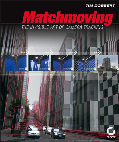
Matchmoving: The Invisible Art of Camera Tracking 2nd edition
Tim Dobbert


THE book about matchmoving. All the nitty-gritty details behind the magic.


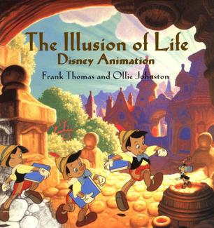
Illusion of Life: Disney Animation
Frank Thomas & Ollie Johnson


A very nice book about Disney studio history and animation in general.


Digital Video and HD: Algorithms and Interfaces 2nd edition
Charles Poynton


Book about everything in digital video from aquisition to colour science to video compression schemas to whatnot. This book already arrived, others are waiting in line.

Tuesday, August 13, 2013

Programming continued... vol 4

Have to start working now, so maybe last update in some time.

Latest improvements:
  • plugin system :)
  • ops with geometry operations
  • 3D view
  • viewer Op options for style overrides, also enables sorting of viewed table
Plugin system is a must in any program worth it's weight, so with some fiddling and hatchetwork I pulled this off. Program now checks the /plugins directory at startup and loads .dll libraries that comply with Op interface. From app side this works nice and easy, plugin development on the other hand is, in lack of better word, interesting. To make use of my nice knobs or in fact any other functionality in main app, all source files must be also added to plugin project. This gets them to compile but each plugin is as big as the application itself! Each file references functions in other files and makes this whole thing a bloody tangled mess. I believe it could be possible to make plugins that don't need to clone the whole program to work. At least other people can make this work...Clearly my lack of programming skills is showing its face here :)

In addition to ops with tables, new ops that create or modify geometry are now in place. Started coding a simple library of geometric primitives also, so that generic functions could be used on all of them for inserting vertices etc.

3D view is working as a proof of concept at the moment. Nothing special there and no 3D ops yet. Works on OpenGL.

Viewer Op is now officially an Op and so came functionalities. One can do style overrides, enable sorting of data tables and force points and lines to show constant size and width.

Ahaa, almost forgot! ComboBoxes and other knobs can update their content, for example Combo that lets user select a column for some operation now updates its values from input.


Thursday, August 8, 2013

Programming continued... vol 3

Long time ago I crossed my limits of understanding in programming, but still, through luck and nice findings I still keep fiddling with my little project. During last week I have come from Qt's "Elastic nodes" example to something that almost looks like a functional prototype.

Biggest improvements are:
  • major UI overhaul from node-editor to multiple dockable areas that contain DAG view, table view and node properties
  • knob callbacks work! With some pure luck I managed to get the callback thing working
  • knobs can be added to Op with only one line of code in Op::knobs method
  • new Ops: simple sort (column and direction) and SQL queries
  • nodes can be attached to existing edges by dragging
  • keyboard shortcut to connect viewer to selected node
  • properties view shows knobs for added nodes. Node parameters subwindow can be closed and opened again by double-clicking the node and last opened is positioned on top. 
UI is now based on dockable widgets so that layout can be changed. Look is customised with stylesheet file.

Knob callbacks work nicely, the idea how it should work came one morning and I quickly scribbled some code on a piece of paper. It worked without zero modifications! Adding knobs is very similar to how it works with Nuke plugin development. Syntax is like: "String_knob(callback, &value, label);" where callback is a knob_callback pointer, value is Op variable that is associated with knob, and label is knob label. Knobs get added into row layout that takes care of label and knob placement. In addition I created functions (Nuke style again) to modify last added knob. For example ADD_VALUES(callback, "Ascending, Descending"); adds value list to last knob (ComboBox or similar). Knobs show tooltips and whole node subwindow shows help info when you click on ? button :)

SQL queries took some fiddling with my datamodel because at the moment it is built on QStandardItemModel. To make queries I have to push items into sql database (QSQLITE internally), make the query, and then put items back to model. All Select commands work great but for some reason I can't get queries that modify table structure or delete row to work. They execute when they are hardwired into code but through UI these queries just don't work.

Node area got some love also, because I was annoyed by dragging every connection manually. So now nodes can be inserted into existing edges. One thing is yet to do with node editor - ability to resize backdrops. At the moment they show the resizing dot in the corner but resizing is not working.

Monday, August 5, 2013

Programming continued... vol 2

Getting into exciting stuff now :) Added TableOp base class for operations on data tables and also created three basic operations that subclass TableOp: read table (from comma-separated textfile), select rows, append rows. Ops have pure virtual function called "engine" which calls all node inputs (and through node->execute() calls  their ops) and queries for input data. Data is asked by these calls up to input nodes (read or create nodes) and from there it pours down again. When all node's inputs are executed, node can also execute its ops. So node graph evaluation and execution are not really tied together. Graph evaluation serves the purpose of detecting circular dependencies and displaying order of operations.

Next step is to add table view into main window, because this floating piece is not very nice, and to add possibilities to edit node parameters through UI. I think it needs some kind of callback mechanism but I am not sure yet how to approach this and whether the signal-slot stuff works for it. Main problem is that each node must define its own knobs and there must be connection between every instance of node, it's knob values, and instance's variables.

Saturday, August 3, 2013

Programming continued... vol. 1

Continued my coding tries and added some functionality:
  • nodes can be deleted :) with proper edge handling
  • inputs-outputs reconnect automatically after node deletion and follow main inputs ("B", the base)
  • pressing Ctrl button displays edge break dots (similarly to Nuke) which can be clicked to create new dot nodes
  • nodes can be selected with box select and moved together
  • edges are displayed with A, B or similar signs if necessary
  • when node is selected, all input edges get nicely colored
  • when edges are reconnected, graph is evaluated and resulting list is displayed on screen
At first I used QGraphicsView default functions for handling node selection, moving and box selecting but as I built more and more on top of it, I screwed something up. For example, when moving selected nodes, they jumped to strange places. I ended up writing all mouse interaction functions myself. Some things are still broken, for example pressing Ctrl while dragging selectionbox cancels selection but box is not deleted properly.


PS: for some strange reason Photoshop makes printscreen images fuzzy. Paint on the other hand gets them pixel-sharp. Very strange...

Thursday, August 1, 2013

Dusting off my programming skills

After ages of thinking over it, I finally started (again) with the prototype of my magic software project. It is not related to vfx but is heavily influenced by node-based compositing software and uses the dataflow programming approach as the main principle. I use C++ and Qt framework for GUI, because it is very easy to use and has lots of good examples.

I started with implementing some very basic node and edge manipulation where one can move, add and remove nodes and edges. In addition it has simple functions for node graph sorting - in what order must the nodes be executed. Sorting is not based on any certain algorithm (although it most probably matches one). Idea is based on node stack, where sorting starts from bottom (Viewer node). Active node is put to evaluation list (that holds evaluated nodes), gets removed from stack, and all it's inputs get pushed to stack. Topmost node in stack becomes active node, is put to evaluation list, removed from stack, and questioned for inputs. If it has inputs, all of these get pushed to stack and so on. If stack is empty, we have evaluated all nodes. After that we reverse the evaluation list and remove items that are already visited through joining graph branches. It seems to work nicely and logic is easy to understand, and what is more important, it avoids evaluating branches that do not contribute to output.

When creating new edge, it also detects circular dependencies. First it sorts the graph beginning from starting node of new edge and then searches the sorted list for end node. If end node is in that list, it means that there is circular dependency and edge is not created.

I started testing the plugin interface but could not find a good way for creating an arbitrary number of parameter knobs (as specified in plugin) and exchanging the parameters between UI and plugin. I can create widgets that are specified in plugin but don't have a good way to pass parameters back and forth when number and type of parameters is set from inside the plugin.

Little teaser also :)

Monday, July 15, 2013

History of aspect ratio

Found this nice video by FilmmakerIQ that explains the historical evolution of aspect ratio:

http://vimeo.com/68830569

Same user has more interesting videos on his channel, for example "The Evolution of Modern Non-linear Editing".

Monday, July 1, 2013

Using STMap based deformations for Lens Distortion workflow

This post is about the full workflow for creating, modifying and applying STMap deformation images for lens undistortion and redistortion. It is meant for Nuke <> SynthEyes exchange but works with other matchmoving apps too (if you know how to apply and remove distortion there ofcourse).

Before getting to the "real thing", some background info about STMaps and their use for (un)distorting images.

For applying or removing lens distortion there are basically two ways:
  • using a matching function and coefficients that descibe the lens distortion characteristics mathematically
  • using a deformation map that describes where every input pixel should end up on output image

Mathematical lens analysis is usually the first step because it is more precise. It could also be possible to make an interpolated deformation map by simply analysing test grid image but it is not that good method and as higher-order fitting is quite fast these days, lens is usually first described with functions and coefficients.

If it is easy to describe lens with distortion function, why would one bother to use a deformation map at all? Answer is simple - as each matchmoving program uses different lens models and compositing softwares have their own models and filters, it becomes hard to exchange lens distortion info. For example, we can matchmove our undistorted plate in SynthEyes or 3DEqualizer or wherever and get a good track, but if we are not able to distort our cg elements to match the original plates then we can't do the composite. It would be highly impractical and often impossible to push all our elements through matchmoving software simply to distort the images. It is much easier to do distorting in compositing application but how to get our genius lens model in there?

STMap comes to resque! As it is simply an image that tells us where our pixels end up, it is basically software agnostic and can be made to work in almost any compositing software that has image-based deformation filter. How crazy our lens model might be, in the end it simply shifts pixels and thus can be baked into deformation image.

All this goodness does not come without price though... It is very cumbersome (or should I say practically useless) to use deformation maps for fixing or applying changing distortion. Zooming and focusing can change the lens distortion parameters and interpolation between two maps is very hard to do. Function based lens models are much easier to manipulate if one needs to animate distortion changes.

With all this info we can start getting into stuff.

Basic order of operations for this is:
  • film the test pattern for SynthEyes Lens Grid auto-calibration
  • create new lens preset
  • generate STMap base image in Nuke
  • apply undistortion (with padding) to generated base image
  • generate STMap base image for redistortion
  • apply distortion to generated redistortion base image

After this is done, you can:
  • undistort original distorted plates using undistortion map
  • apply distortion to cg elements using redistortion map

Using STMap based distortion in one step (undistort or redistort) should be more or less the same quality as for example LensDistort node. Still bear in mind that errors in choosing high enough bit depth for distortion map images or some out-of-nowhere applied gamma correction can make your life miserable and introduce ugly artefacts.

Test pattern and lens preset creation in SynthEyes

Download the test pattern for SynthEyes Lens Grid auto-calibration and follow instructions in this video:
Lens Grid auto-calibration by Russ Andersson from SynthEyes.

Save lens preset and don't forget to name it so that it points to both the lens and zoom level if necessary.

STMap base image generation in Nuke

Create a new Constant image with the size that matches your plate photography (it can also be bigger but it is easier for description purposes to use the same size).


Apply Color > Math > Expression node with these equations:
r = (x+0.5) / width
g = (y+0.5) / height

This creates an image where red and green channel contain normalised x and y coordinate values. Adding 0.5 to coordinate value is important because it fixes the offset introduced by interpreting the pixel position as centered in STMap node (thanks to Jarrod Avalos for pointing it out).


Save this coordinate image as either a float / half-float exr or 16-bit tif. For tif, you must click "raw data" checkbox in colorspace settings or choose "Linear", otherwise Nuke applies gamma correction and image gets messed up.

Apply undistortion to generated base image

Load the generated base image in SynthEyes, don't forget to set bit depth according to format - for exr choose float for example.

In Image Preparation dialog choose the correct lens preset from dropdown in Lens panel.


In overall Summary panel click the Lens Workflow button and choose Redistorted(2). Base image gets "undistorted" and overscanned - it gets bigger to fit all the "undistorted" pixels.


Save the "undistorted" image by clicking the Save Sequence button. Choose exr or tif as format and follow the rules described earlier.

Generate base image for redistortion

Create a new Constant image with the size that matches the "undistorted" base image. It is larger than original plate photography.

Apply Color > Math > Expression node with these equations:
r = (x+0.5) / width
g = (y+0.5) / height

Save this image as either a float / half-float exr or 16-bit tif. For tif, you must click "raw data" checkbox in colorspace settings or choose "Linear", otherwise Nuke applies gamma correction and image gets messed up.

Apply distortion to redistortion base image

Load the redistortion base image in SynthEyes, don't forget to set bit depth according to format - for exr choose float for example.

In Image Preparation dialog choose the correct lens preset from dropdown in Lens panel and click the Apply Distortion checkbox. Image gets distorted as if projected through the lens.


Save the "distorted" image by clicking the Save Sequence button. Choose exr or tif as format and follow the rules described earlier.

---------------------------------------------------------------------------------------------

After all this is done, we have a map that helps to undistort plate photography and a map that helps to distort cg elements to match the plates.

Undistorting plate photography with STMap

To undistort original plates one simply has to apply the STMap operation to plate and connect the undistortion map to it's stmap input. Resulting image is as big as the undistortion map (larger than original image).


Distorting cg elements and whatnot with STMap

To distort elements one has to apply the STMap operation to element and connect the distortion map to its stmap input. Resulting image is as big as the undistorted image. To make it match plate photography for example, simply add a Reformat node with "type - to format" and "resize type - none, centered" settings.

EDIT: cropping to center with Reformat only works when lens is not decentered. When there is offset, make sure that you shift the image properly! This method does not compensate for decentering. Another way is to choose redistort cg and select the larger stmap base image. Results are very similar to original but for some reason do not match exactly.

Please note that all your cg elements must be rendered out larger than original plate photography - their size must match the distortion map. As matchmove is done on undistorted plates, camera fov and other settings are also based on this larger undistorted image size.

End of story

I hope this description makes it a bit more clear how to apply and remove distortion using STMap node and deformation maps and how to generate ones to begin with. There are not that many descriptions of this technique in the internet and although it is rather easy, it can take some fiddling to get it working.

Some sites discussing the same topic:
Nukepedia tutorial by Florian Gellinger from RiseFX
VFXTalk forum talk about PFTrack > Nuke

PS. if someone knows an easy way how to generate distortion maps from undistortion maps and vice-versa, it would be nice to know! STMap does not have the reverse button as LensDistortion node has although it could be quite useful. It should be pretty straightforward pixel math but as with everything, it takes some moments of thought. If I find the solution I will post it here.

Friday, June 7, 2013

NUK222 keying exercise

fxPHD April term courses are running nicely. I tested some different approaches in keying scanned film footage from NUK222 class and got pretty decent results. Main problems were edge boiling due to film grain and restoring hair detail but with some fiddling I got an ok result for hair and pretty nice edge for dark jacket.

This is the original and my result on neutral background (click for pixel-per-pixel zoom):

Node graph:


I tried to keep node graph organized and tidy. Key section pulls the main key with two Keylight nodes and inputs from different denoising. Hair matte manipulation is for main hair detail from keyers and blurs and erodes the edge for blending with hair element from hair detail section. Hair detail generates non-alpha hair that is comped onto background under fg. Jacket patch is for removing boiling on the dark jacket edge. It could be made simpler by patching the key instead, at the moment it generates a jacket-colored patch that is comped under fg to fill edge holes.


Thursday, May 9, 2013

Running .bat and python scripts from Backburner

Some notes about running scripts through Backburner. Why do that? To make some crude automation with files or databases - for example run render first, then check if output is ok, then generate preview movie clip, then upload relevant info to database (Shotgun for example).

It seems that Backburner does not like .py files, it throws error code 193 meaning it is not a valid executable. You can get around it by wrapping python script into .bat file. Bat files run ok and can pull python up nicely.

Monday, April 29, 2013

PixelConduit

Found this nice "little" software called PixelConduit that can do live video feed manipulation and compositing. It uses node-based workflow and can also work with stereo inputs, multi-display output, queing, staging and a lot of other stuff. Unfortunately it seems that it is for Mac only... Pricing for full version is 119$ which is really cheap for what it can do.

Homepage: http://lacquer.fi/pixelconduit.html

Friday, April 26, 2013

Lots of reading

Last week I finally received my new books that I ordered through Krisostomus bookshop. The books are:

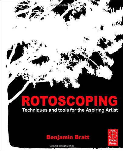
Rotoscoping: Techniques and tools for the Aspiring Artist


Rotoscoping tips-tricks and general workflow handbook by Benjamin Bratt. How to roto more efficiently and get consistent high quality results.

VES Handbook of Visual Effects


Book by Jeff Okun and Susan Zwerman, covers all visual effects aspects and is intended to be kind of a "bible" that describes current industry standards and practices.

Visual Effects Producer: Understanding the Art and Business of Visual Effects


By Charles Finance and Suzan Swerman. About the management side of visual effects from planning to execution.

All three seem to be really good and insightful books, I hope that I get some time to write my own little reviews for all three of them.

Thursday, April 4, 2013

Backburner render manager and Blender

I started wondering, how to get Blender renders to Autodesk Backburner render manager and it turned out to be quite easy. Backburner is the free render manager-server-monitor system that comes with 3DS Max, Maya and other Autodesk projects and can also accept any other command line executable input. Autodesk products can submit jobs directly from the program, other software need a plugin or one can submit jobs through command line tool called cmdjob.exe.

So how to do it with Blender

Basically it is very easy. Submit command looks something like this:

"C:\Program Files (x86)\Autodesk\Backburner\cmdjob.exe" -jobName "submitBlenderJob" -manager localhost -priority 50 -numTasks 1 "C:\Program Files\Blender\blender-2.66a-windows64\blender.exe" -b "C:\projekt\stseen.blend" -a

It breaks down into four parts:

cmdjob.exe <cmdjob parameters> <program executable> <program parameters>

Program parameters are the usual command line rendering arguments that can be found in Blender wiki or for other programs (AfterEffects for example) in their help documents.

cmdjob argumens can be found here:
http://download.autodesk.com/us/systemdocs/pdf/backburner2011_user_guide.pdf

some info about tasklists and dividing up jobs:
http://docs.autodesk.com/3DSMAX/16/ENU/3ds-Max-Help/index.html?url=files/GUID-F23992DB-19BD-423A-A97C-5CC157328E63.htm,topicNumber=d30e554791

Blender command line arguments:
http://wiki.blender.org/index.php/Dev:2.5/Doc/Command_Line_Arguments

Backburner 2012 installer:
http://usa.autodesk.com/adsk/servlet/ps/dl/item?siteID=123112&id=17888178&linkID=9241178

At the moment I use Backburner for scheduling AfterEffects and Blender jobs and it seems to work fine. You can also add e-mail notifications about success and errors which can be very handy.

Thursday, January 24, 2013

Bayer sensor image upscaling

An interesting thread has popped up on BMCUser forum that talks about upscaling bayer pattern sensor images (or any other image really). Some great examples and sample files also. It involves luma-chroma conversion, Nuke TVIScale lambda scale and smoothing and dithering of certain channels. Results speak for themselves - moire patterns seen on usual debayered image that get magnified when upscaled are practically gone. It was even mentioned that when comparing 2.5K upscaled image with Red One image and Red's own debayer, BMC image needed some blur to be of similar softness...

An example also, extracted from sample images in the forum (click to view original size). 4K is at 200% zoom and original 2.5K image is zoomed to fill same area: